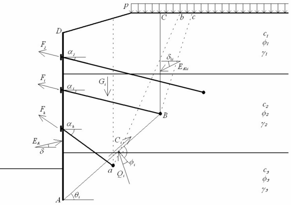
Internal Stability of Anchors
The internal stability of an anchorage system of sheeting is determined for each layer independently. The verification analysis determines the anchor force, which equilibrates the system of forces acting on a block of soil. The block is outlined by sheeting, terrain, line connecting the heel of sheeting with anchor root, and by a vertical line passing through the center of anchor root and terrain.
The theoretical footing of sheeting construction is the point where the sum of horizontal forces under the bottom of the construction pit is equal to zero. If this point lies under the footing of the sheeting wall, the theoretical point is the footing of this wall.
The analysis is performed per one running meter of a sheeting structure. Anchor forces are therefore computed with respect to their spacing in individual layers.
 Analysis of internal stability
Scheme for verification of the ith layer of anchors is shown in the figure. The force equilibrium for the block ABCD is being determined. The following forces enter the analysis:
EA | - | resultant of active earth pressure acting on sheeting (on line AD) |
EAi | - | resultant of active earth pressure above the root of verified anchor (on line BC) |
Gi | - | weight of the ith the soil block ABCD; in addition, this value incorporates the surcharge p applied on the ground surface providing the slope θi of slip surface AB is greater than an average value of the angle of internal friction on this surface; in case of a smaller slope of slip surface AB the ground surcharge is not considered |
Ci | - | resultant of soil cohesion on slip surface AB |
Fj, Fk,… | - | forces developed in other anchors, but some of them are not taken into account; only "shorter" anchors (comparing with the ith anchor) will contribute in the equilibrium analysis of the ith block; following principle is used to decide whether the given anchor (the mth) is included or excluded from the equilibrium of the ith block: at first the lower anchor is selected (the mth or the ith); then a plane slip surface is placed from the root center of the selected lower anchor; this plane is inclined 45o - φn/2 from vertical line (line ab or Bc in the figure); φn is an average value of the angle of internal friction above the root of the lower anchor; if the ith root is found above the mth one and the higher located root (the ith) is outside the area cut by the plane slip surface, then the mth anchor is included into analysis; the same example of including the mth anchor is when the ith root lies under the mth one and the mth root is located inside the area cut by the slip surface; two opposite cases determine excluded anchors from analysis; first is the ith root above the mth one and the ith inside the area, second is when the ith root lies under the mth one and the mth is outside the area; from above definition resulting that "shorter" anchor Fk is included into analysis and "longer" anchor Fj is excluded from analysis (see figure) |
Qi | - | reaction on slip surface AB |
Fi | force in the analyzed anchor, the maximum allowable magnitude of this force is the result of the equilibrium analysis carried out for the ith block |
The solution of the equilibrium problem for a given block requires writing down vertical and horizontal force equations of equilibrium. These represent a system of two equations to be solved for the unknown subsoil reaction Qi and the maximum allowable magnitude of the anchor force Fi.
As a result, the program provides the maximum allowable anchor forces for each row of anchors. These are then compared with those actually prescribed in anchors.